The QTH at G3YMC is in a typical suburban estate with terraced houses on all sides and a back garden of 15m x 7m. It is not practical to use the front of the house so scope for antennas is limited. A loop antenna seemed the ideal answer.
I have used receive frame antennas on 73kHz, and they offer a good receive antenna in a very small space.
A transmit loop is basically similar, except that it is very much bigger and normally has only a single turn of wire. The idea is to launch the magnetic component of the signal into the ether, and it converts itself into a full electromagnetic wave with E and H components in the far field.
With any antenna on the lf bands there is a battle with extremely low radiation resistance and resistive losses in the system. Radiation resistance is low since antennas are usually only a fraction of the wavelength (although some amateurs now have 136 antennas approaching a quarter wave, eg. OH1TN).
The following calculations assume classical loop
theory. Mike Underhill G3LHZ has done extensive work on loops and
has found this classical theory just does not agree with the performance
he has achieved. See below for alternative formulae
for loops which Mike has derived.
| The radiation resistance of a loop antenna
can be found from the following formula:
Rrad=320 *(pi)^4*(A)^2/(L)^4 That is, radiation resistance equals 320 times pi-to-the-power-4
|
 |
The QTH at G3YMC is in a typical suburban estate with terraced houses on all sides and a back garden of 15m x 7m. It is not practical to use the front of the house so scope for antennas is limited. A loop antenna seemed the ideal answer.
|
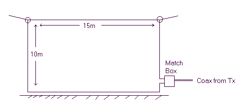
It was decided to use the whole of the garden for the loop, which allowed a loop with a wire length of 45m, and an area of 100 sq.m., which is considerably larger than some of the other loops (ref. G3LNP, G3LDO) which have been used on the band. The first loop put up used ordinary 19/.76 wire, but the resistance of 45m of this is about 1.2ohm, and it rapidly became apparent from the reports received (or lack of them) that the efficiency was very poor at about .001% with radiated power of microwatts.
The wire was then replaced with heavy duty loudspeaker cable with the pairs connected in parallel, to give an effective wire cross-section of 5mm.sq. and a measured dc resistance of less than 0.1 ohms. In fact the effective resistance at 136kHz is rather higher due to skin effect and other considerations. Measurements (see later) show that this is in fact 0.65 ohms.
The loop here is a rather dog-legged construction. One end is supported by a 10m pole by the house, the other end is at only 5m, since rear guying of a pole there is not possible. The wire is run in a sort of rhombus between these points, with the lower sides running along the garden fence about 0.3m above ground. The loop is fed at one corner at ground level, via a matching box screwed to the wall of the house (see later). The dimensions in the diagram are given as a guide only.
This puts into perspective the problem of radiating on 136!
 |
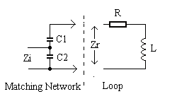
The loop presents an inductive impedance together with a loss resistance, Zr=R+jwL. Two capacitors C1 and C2 are used in the matching network, to form a capacitive divider which resonates the antenna and divides the impedance down to Zi. |
The impedance of the loop at resonance depends on its Q, ie the loss resistance, the higher the Q the higher the impedance. To divide this down to 50 ohms requires a relatively large (parallel) capacitance across the feed cable and a rather smaller capacitance from this point in series with the loop wire.
More information on matching networks for loop antennas, including a computer program to do the sums, can be found in the 'LF Experimenter's Source Book'. This is unfortunately now out of print, the new 'Low Frequency Experimenter's Handbook', available from the RSGB, which supercedes it does not cover transmit loops.
The present G3YMC loop requires a 22nF capacitor for C1 and a 200nF capacitor for C2. The types of capacitors used are very important. I use Philips polypropylene types from their 376 series - these are available in various voltage ratings up to 2kV. Philips 378 series capacitors may also be suitable, but the 376 has a much better specification for handling pulse currents. Initial use of Wima metallised polyester capacitors for the parallel component were somewhat disappointing as these soon went lossy and overheated (I actually blew one up).
The bandwidth of the loop is quite small, and it is only possible to move transmit frequency by some 100Hz either side of resonance before retuning is necessary, which is done with several small switched capacitors inside the matching box selected with miniature toggle switches. If you put up a loop and find it is quite broad there is something wrong with it. Surprisingly significant is the temperature coefficient of the capacitors - the change in temperature between early morning and mid day results in a resonance change of some 200 Hz hf, and in the cold winter mornings there is appreciably shift lf.
Reg G4FGQ has written a couple of programs to calculate the performance of single turn transmit loops. RJELOOP1 and RJELOOP2 may be downloaded from his web site. Although aimed at hf transmitting loops which are normally fed via a coupling loop and not the capacitive network used by myself, they give a remarkably good simulation of the loop, calculating the loss resistance fairly accurately.
Note the magnitude of the current - at my normal 35W it will be nearly 8 A - and if I were to use 400W 26 A would flow. It is clear that there will be significant heating of the matching capacitors at this level, and use of suitable capacitors is most important.
Another advantage of loops is that they tend to pick up far less local noise than other antennas. In many locations local QRN is very much a limiting factor in receiving stations, with all manner of potential sources such as TVs, computers, low energy light bulbs to mention but a few. Since loops pick up the magnetic rather than the electrical field they offer a good low noise receiving antenna. At G3YMC my long wire is useless during darkness hours with a S9 plus noise level. The noise on the loop is usually no more than S7.
A further advantage of loops is that they are relatively unaffected by detuning caused by rain and the elements. Vertical and Marconi antennas detune significantly under varying weather conditions, whereas loops seem to be far more stable (except for temerature drift in the capacitors as mentioned above).
The big disadvantage of loops is that they are very directional, with a sharp null in the plane of the loop. This means that although they work very well off the ends, they are very disappointing broadside on. The loop at my QTH runs SSE/NNW. However a null in the direction of a local noise source could be an advantage.
The radiation resistance of the loop, and hence the radiated power, is proportional to the square of the area, so the bigger you can make this the better it will work. It has also been suggested that making a two or three turn loop with the wires spaced a few inches will offer an advantage, and experiments have been carried out by some stations using such an arrangement. Some have indicated that theory proves that a two turn loop will work identically to the same loop made of thicker wire of twice the area so effort should be made to reduce the series resistance element instead. Other users have in fact shown that a two turn loop does indeed offer a slight advantage.
To summarise, a loop is certainly an antenna to be considered where space is limited, but where a vertical or Marconi antenna is possible this may well give better performance, which has been confirmed by quite a few operators on 136.
It is interesting to do comparisons between received signals on my loop and my 60ft longwire and vertical antennas. Stations in the line of the loop are typically 10-15dB better on the loop than on the other antennas. However stations in the null are some 10-15dB better on the longwire or vertical. This indicates the null is around 30dB.
I am quite pleased with the performance of the loop. It certainly
offers an antenna for small QTHs where large antennas are out of the question.
I have now constructed a top loaded vertical as an alternative antenna
which is described here. Initial results
indicate the problems of using verticals when the ground resistance is
poor, and the loop remains the best antenna for most directions.
Alternative Loop Performance theory by Mike G3LHZ
The following information has been supplied by G3LHZ and indicates the performance of my loop is considerably better than conventional theory indicates. Note that this information is somewhat controversial, and I do not necessarily imply that my loop performs in the way indicated! The formulae are quoted as received from Mike.
The Q of a loop, assuming resistive losses are zero, is shown to be Q = 500/D, where D is the diameter of the loop in metres, or for a rectangular loop like mine, the circumference divided by pi.
For my loop, D = 45m/pi = 14.3m
Q (limiting) = 35 Effective 3dB bandwidth = 3.9kHz
The Q will in practice be rather less because of dc loss resistances.
The matching bandwidth of my loop also indicates this Q is rather pessimistic.
The inductance of a loop is given by the formula L (uH)
= pi D^1.16 / (160d)^0.16
where D is the loop diameter or circumference/pi
in metres
d is the wire diameter in metres
For my loop, D=14.3m, d=.0036m
L = 75 uH
Which agrees well with the measured value of 70uH
The radiation resistance of a loop is given by the formula R(looprad) ~ = LoopArea * f (MHz) / 20
For my loop, R(looprad) = 0.68 ohms
Although this radiation resistance is very much larger than the traditional
theory figure, in order to calculate loop efficiency, the real earth loss
resistance must be used - in my case 300 ohms.
Efficiency = 0.68/(300+.68+.65) = 0.26%, a more reasonable
figure
Radiated power for 35W input = 79mW
These alternative formulae for loops indicate they should work considerably
better than conventional theory indicates, and certainly the results with
my loop confirm this. However these formulae were derived from measurements
of hf circular loops, and they may not be correct for lf rectangular loops.
I have a feeling they predict my loop performance rather too optimistically.
| Operating | Experimental Vertical | 136kHz Equipment | 136kHz main page | Home Page |