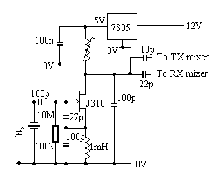
The oscillator is powered from a stabilised 5V rail provided by a 7805 regulator to ensure stability.
The two output capacitors may be adjusted in value to obtain the correct injection levels.
No originality is claimed for the design. It was built up using published circuits in the ARRL handbook and elsewhere, modified ad hoc for the application. It has been used for several years now, although with anything which is experimental it has seen various changes and repairs. The receive side has been in use rather longer as a 73kHz converter, although I never got round to getting a transmit NOV permit for that band.
The circuit is described in blocks, with all components shown but no details is given on the inductors and transformers except for general guidelines. It is intended as an experimenter's unit rather than something available off the shelf, although it has been suggested that it could be made into a kit.
See my Equipment Practices page for a discussion
of the relative merits of transverters over other equipment for 136.
 |
A 10MHz JFET crystal oscillator is used.
This is a conventional circuit and outputs a reference to the receive and
transmit mixers. A trimmer capacitor can be used to set the frequency accurately.
The oscillator is powered from a stabilised 5V rail provided by a 7805 regulator to ensure stability. The two output capacitors may be adjusted in value to obtain the correct injection levels. |

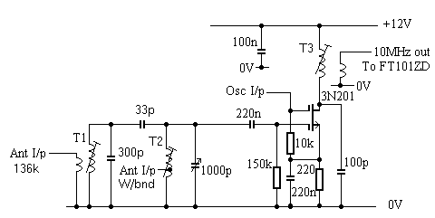
| Input from the antenna is applied to a fixed tuned stage, T1.
This transformer uses a cut down long wave ferrite rod from a scrap radio
and resonates in the 136 band with a parallel capacitor of around 300pF.
This is top capacitive coupled to a second tuned stage (using a pot core)
which can be tuned from 65-180kHz with a dual 500pF variable capacitor.
An input is provided here for a wideband reception antenna, eg for 73kHz,
but at lower intermodulation performance. The preamp which I used
to use has been removed as it tended to overload when fed from my vertical
antenna.
A 3N201 dual gate MOSFET is used as the receive mixer, with the oscillator injection applied to G2. This is conventional with the drain resonated to 10MHz by T3, wound on a quarter inch former. |
| 136 Main Page | Loops | Equipment Practices | Bracknell ARC | Transmitter | Homepage |